I’ve spent the last couple of years designing and building out the Azure environment for my employer. It’s been an amazing journey and I’ve learned a huge amount along the way, especially with respect to networking. I’ve also uncovered a couple of aspects of Azure networking with peered VNETs which I feel are very poorly documented and also have significant design implications if you’re building a peered hub-and-spoke network environment within your Azure space.
This post outlines what I’ve found, details the impact that it has on the design and provides some guidance on what a correct implementation looks like with those behaviors in mind.
Background: Hub-and-Spoke networking in Azure
Hub-and-spoke networking is a topology design where a single “hub” VNet is connected to one or more “spoke” VNets via VNet peering. In this design the spokes typically are not peered to each other. This is becoming a fairly common design which has a number of advantages. For example, it allows all of the networks to share an external connection that is established from the hub such as an ExpressRoute link or VPN S2S tunnel. The connections from hub to spokes are also extremely fast because the data flow is made entirely within the Azure network fabric and doesn’t need to pass through any compute instances for processing as it does with a VNet-to-VNet VPN link.
A Virtual Network Peering is a durable connection which needs minimal attention after it’s created and doesn’t require deploying any infrastructure to manage, unlike a VPN gateway for example. Peering must be initiated from both VNets for data flow to be established. For a walkthrough on how to create a VNet peering, see <this link>.
In the diagram below, “A” and “C” are spoke VNets and “B” is the hub VNet. The hub VNet has a gateway in it with a connection to an external network
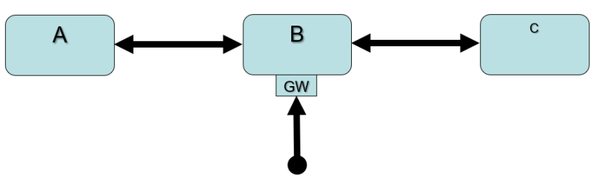
Gotcha #1: Peering relationships are NOT TRANSITIVE
When creating environments such as the one above, it seems natural for the person looking at it to assume that connections from one spoke to another are made by relaying the traffic through the hub’s VNet. However, this is not the case because VNet peering relationships are not transitive.
In other words, traffic from a host on spoke VNet A has no route to a host in spoke VNet C unless the two spokes are directly peered with each other – sometimes but not always a desirable configuration – or routing “intelligence” is somehow added inside the hub VNet B to forward traffic arriving from one spoke to the other spoke.
Gotcha #1 Workaround, part 1: Add the part that Microsoft (literally!) leaves out
Microsoft’s documentation on implementing a hub/spoke network topology seems to always include a diagram like the one below which shows a virtual appliance (NVA) in the hub VNet but it’s never clearly explained what the role of this device is: to provide routing between the spoke VNets.
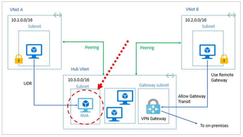
There are two pieces to making traffic between spokes flow cleanly: First, you need to deploy something to provide the routing.
In my case, we have a requirement that traffic between subnets within Azure must pass through a firewall for inspection. We are using a Palo Alto virtual appliance in our hub VNet for this purpose and, fortunately, these have built-in intelligence to provide the missing routing functionality and PA’s documentation on how to configure their virtual firewalls in Azure has the correct setup instructions to make things work as you expect with respect to routing.
Gotcha #1 Workaround, Part 2 (and introducing gotcha #2)
Simply adding a device with routing capability to the hub VNet does not completely close the gap with respect to making traffic flow smoothly from one spoke to another.
What is required is for the spoke subnets which need to talk to each other to have a route table entry which specifies that traffic destined for other spoke subnets uses the IP address of the virtual appliance as the “next hop”.
In the diagram above, subnet A needs to have a route table entry which states that traffic for subnet C’s IP block has a “next hop” address of the appliance in VNet B and subnet C needs a route table entry which sends traffic to subnet A’s IP range to the same “next hop” IP.
In a large environment with lots of subnets, the route tables can accumulate numerous entries but the same route table is used on all subnets so the table’s definition can be kept in an ARM template to make deploying and updating the tables relatively safe and easy.
Wow, that’s nasty…
You’re probably thinking right now that simply applying a default route entry to the route tables on every subnet would be a lot easier than specifying each internal subnet separately.
It’s completely logical to assume that you can simply throw a 0.0.0.0/0 à <virtual appliance IP> as the single entry on each subnet and let things roll, but in reality that doesn’t work because of gotcha #2.
Gotcha #2: Peering relationships take priority over default routes between peered VNets
This is another aspect of VNET peering which needs to be documented much more clearly by Microsoft.
Buried inside the third “note” block on Microsoft’s tutorial on creating a hybrid network environment with the Azure firewall (under Prerequisites) is the following quote:
“Traffic between directly peered VNets is routed directly even if a UDR points to Azure Firewall as the default gateway. To send subnet to subnet traffic to the firewall in this scenario, a UDR must contain the target subnet network prefix explicitly on both subnets.”
This has implications far beyond the context in which this statement appears. It means that using default routes in UDR’s on peered VNets is pointless because traffic between peered VNETs that does not have a specific destination specified in a UDR listed will always flow through the peering relationship to the other VNET even if a default-route UDR entry is present.
Make sure to plan with this behavior in mind for your design as well. This is why, in the routing examples above, simply putting a 0.0.0.0/0 UDR on each of your spoke subnets will not achieve the desired result!
Strangely, this note is the only location that I have found which describes this behavior. It’s not mentioned on the page describing VNET routing or the one on Azure VNet Peering as far as I can tell.
Experimentation is highly recommended!
I built an isolated replica of our VNet environment which matched the diagram at the top of this page: a hub VNet, two spoke VNets, an “external” VNet, a PA firewall and the necessary peering and VPN connections to get the topology working correctly.
I then put VM’s on at least one subnet in each VNET and did a number of tests to see which VM’s could ping which other, initially with no route tables at all and then with various route table configurations to confirm that the behavior I was seeing aligned with the documentation.
Use the Network Watcher’s “next hop” tool to verify that traffic from a particular source is taking the path that you expect to its destination.


You must be logged in to post a comment.